专业网站建设在哪里免费做网站怎么做网站吗
在Verilog中,模块之间的通信是使用模块端口指定的。
Verilog模块连接的缺点
- 声明必须在多个模块中重复。
- 存在声明不匹配的风险。
- 设计规格的更改可能需要修改多个模块。
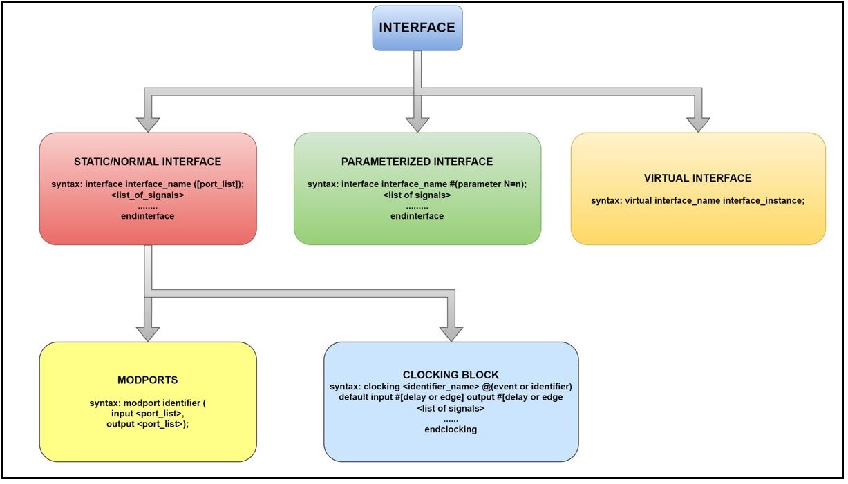
接口
SystemVerilog引入了 interface 结构,它封装了模块之间的通信。一个 interface 是一组信号或线路,通过它测试台与设计进行通信。
| 序号 | 数据类型 |
|---|---|
| 1. | 接口 |
| 2. | 参数化接口 |
| 3. | Modports |
| 4. | 时钟块 |
| 5. | 虚拟接口 |
接口结构用于连接设计和测试台。
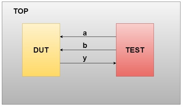
不使用Interface的Systemverilog
下图显示了不使用接口连接设计和测试台的情况。
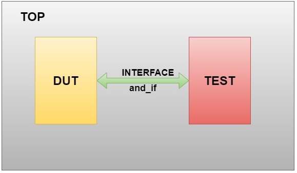
SystemVerilog接口
下图显示了使用接口连接设计和测试台的情况。
语法:
interface (interface_name) ([port_list]);  [list_of_signals]
endinterface
示例:
接口声明
interface and_if; logic input_a,input_b,output_y;
endinterface

这里的接口由一组信号组成,在测试模块中,我们调用接口句柄,但我们没有声明信号的方向。在测试模块中,我们将 a_input 和 b_input 的值传递给接口。在顶层模块中,我们使用接口实例化 DUT 信号。DUT 的输出 ‘y’ 通过接口发送到测试模块。接口中没有使用 modport。我们可以通过在信号上声明 ‘/’ 来声明每个信号的大小。这用于知道信号的矢量大小。
AND门的顶层模块
//Here the interface,testbench,design module are called.module top();//interface moduleand_if inf();//design module instantiateandg a1(.input_a(inf.input_a), .input_b(inf.input_b), .output_y(inf.output_y));//testbenchtb a2(inf);endmodule:top
Design code for AND gate
//module declaration module andg(input_a,input_b,output_y); input input_a,input_b; output output_y; //assign output assign output_y=input_a&input_b; endmodule:andg
Testbench for AND gate
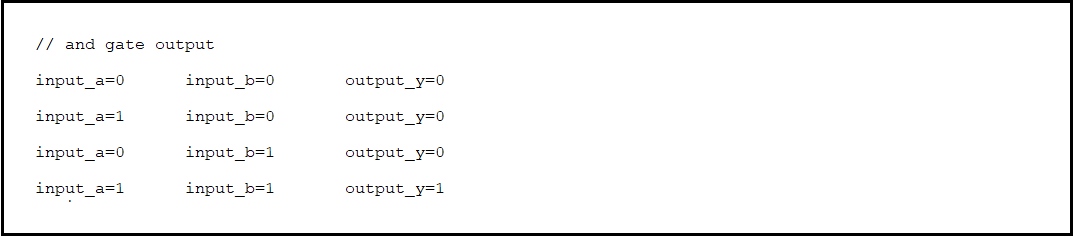
//testbench for and gate module tb(and_if inf); initial begin $display("\n// and gate output"); $monitor("\ninput_a=%b\t input_b=%b\t output_y=%b",inf.input_a,inf.input_b,inf.output_y); inf.input_a = 0; inf.input_b = 0; #1; inf.input_a = 1; inf.input_b = 0; #1; inf.input_a = 0; inf.input_b = 1; #1; inf.input_a = 1; inf.input_b = 1; end endmodule:tb
下图显示了使用接口的AND门的输出。
SystemVerilog接口的优点
- 在Verilog中,添加新信号时,必须手动更改模块实例化的每个地方。SystemVerilog使得在接口块中为现有连接添加新信号变得更加容易。
- 它增加了跨项目的可重用性。
- 一组信号可以通过其句柄轻松共享在组件之间传递。
- 它提供方向信息(modports)和时序信息(时钟块)。
参数化接口
可以在接口中使用参数,使用Verilog的参数重新定义构造使接口内部的向量大小和其他声明可重新配置。
语法:
interface (interface_name) #(parameter parameter_name = initialize);[list_of_signals]
endinterface
示例:
interface count_if #(parameter N=2) ;
logic reset,clk;
logic [N:0] counter;
endinterface:count_if
计数器的顶层模块
//Here the interface,testbench,design module are called.module top();//parameterised interfacecount_if inf();//design code of up_counterup_counter u1(.clk(inf.clk), .reset(inf.reset), .counter(inf.counter));//testbench for up_counterupcounter_testbench u2(inf);endmodule:top
计数器的设计代码
//Design code for up countermodule up_counter(clk,reset,counter);input clk, reset;output [2:0] counter;reg [2:0] counter_up;//up counteralways @(posedge clk or posedge reset)begin//if reset=0 count will be incrementedif(reset)counter_up <= 3'd0;elsecounter_up <= counter_up + 3'd1;end assign counter = counter_up;endmodule:up_counter
计数器的测试台(Test bench)
//testbench for up countermodule upcounter_testbench(count_if inf);initial begin$display("\n // Parameterised interface example");//used to monitor the count values$monitor("\ncount=%0d",inf.counter);inf.clk=0;forever #5 inf.clk=~inf.clk;endinitial begininf.reset=1;#20;inf.reset=0;#70 $finish;endendmodule:upcounter_testbench
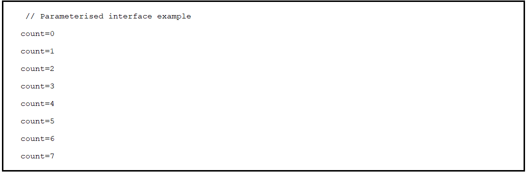
这里我们考虑了3位输出,其中计数器从0计数到7。
下图显示了带有参数化接口的计数器的输出。
通过两种方式可以更新参数值
- 传递常量值
- 使用‘defparam’关键字
传递常量值
在这种情况下,参数的值通过顶层模块实例化接口传递给接口。例如: count_if#(2) intf();
count_if 是接口名称。
#(2)- 是传递给接口模块的参数值。
示例:
接口模块
interface count_if #(parameter N);logic rst,clk; logic [N:0] counter; logic [N:0] counter_up; endinterface:count_if
顶层模块
module top(); //parameterised interface //pass by constant value count_if#(2) intf(); //design code of up_counter up_counter u1(intf); //testbench for up_counter upcounter_testbench u2(intf); endmodule:top
输出
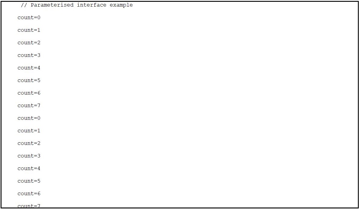
下图中的图,up_counter的输出从0计数到7。这里参数的值通过顶层模块实例化中的接口传递。
使用‘defparam’关键字
defparam 用于通过使用层次名称实例来覆盖参数值。defparam允许在编译时更改参数值。
例如: defparam intf.N=1;
这里intf是接口的句柄。
N是参数。
接口模块
interface count_if #(parameter N=4);// declaration of design signalslogic rst,clk;logic [N:0] counter;logic [N:0] counter_up;endinterface:count_if
顶层模块
module top();//parameterised interfacecount_if intf();//Declaration of defparam defparam intf.N=1;//instantiation of design moduleup_counter u1(intf);//testbench for up_counterupcounter_testbench u2(intf);endmodule:top
输出:
下图中的图8显示,接口参数值N=4。但是通过使用关键字defparam,在顶层模块实例化时,我们可以覆盖参数的值。

模块端口
- Modport 用于指定在接口内声明的信号的端口方向。modport 在接口内部用关键字 modport 声明。
- Modport 是模块端口的缩写。
Modport 的特点:
- 可以具有输入、双向和输出。
- 通过指定端口方向,modport 为信号提供访问限制。
- 接口可以有任意数量的 modport,接口中声明的信号可以分组在多个 modport 中。
- modport 可综合化。
语法:
modport identifier (input <port_list>, output<port_list>);
示例:
interface and_intr;    logic p,q;  logic r;  modport DUT_MP(input p,input q,output r);   modport TB_MP(output p,output q,input r);
endinterface : and_intr
AND 门的顶层模块,在测试台和设计文件中调用 modport 名称:
// creating top module // in this file design,testbench,interface modules are calledmodule top();// interfce module calledand_intr inf();// design module calledand_gate a1(inf);// testbench module called tb a2(inf);endmodule : top
AND 门的设计文件:
// and gate design file // module defination for and gate with interface instanciation module and_gate(and_intr inf);// assign the output using continuous assignmentassign inf.DUT_MP.r = (inf.DUT_MP.p) & (inf.DUT_MP.q); endmodule : and_gate
AND 门的测试台文件:
// testbench file for and gate design// module defination for testbench with interface instanciationmodule tb(and_intr inf);initialbegin$display("// and gate output using modports\n");repeat(5)begininf.TB_MP.p = $random;#1;inf.TB_MP.q = $random;#1;$display("input_p=%b\t input_q=%b\t output_r=%b",inf.TB_MP.p,inf.TB_MP.q,inf.TB_MP.r);endendendmodule : tb
使用接口中的 modport,在上述提到的两种方式下,AND 门的输出保持不变。如下图所示。

时钟块
时钟块被定义为一种机制,用于将输入和输出信号的采样和驱动与时钟事件同步。在测试台内使用时钟块非常有用,可以避免模拟中的竞态条件。我们可以明确地指定信号与特定时钟同步时的时间。时钟块只能在模块、接口内声明。时钟块只涉及输入和输出如何进行采样和同步。将值分配给变量是由模块、接口而不是时钟块完成的。
时钟块术语
1. 时钟事件
clocking 时钟块名称 @(posedge clk);
事件规范用于同步时钟块,@(posedge clk) 是时钟事件。
2. 时钟信号
input  from_Dut;
output to_Dut;
时钟块采样和驱动的信号,from_DUT 和 to_DUT 是时钟信号。
3. 时钟偏移
时钟偏移指定了在哪个输入和输出时钟信号要被采样或驱动。偏移必须是一个常量表达式,并且可以指定为参数。
输入和输出偏移
default input #1step output #0;
默认输入偏移和输出偏移声明如下,default input #1step output #0;。这里默认输入偏移需要 #1step 延迟来获取稳定输入的采样过程。输出偏移仅需要 #0 延迟,这意味着我们在当前时间段内得到稳定的输出。
下图显示了默认的输入和输出偏移。
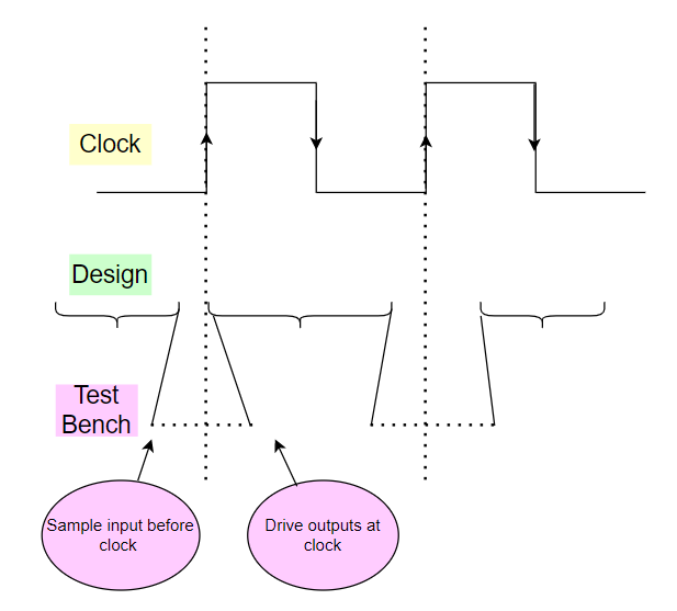
下图显示了输入偏移和输出偏移。

输入信号相对于时钟事件进行采样。如果指定了输入偏移,则信号在时钟事件之前的偏移时间单位被采样。然后,输出信号在相应的时钟事件之后的偏移时间单位被驱动。输入偏移隐式为负,因为它发生在时钟之前。
例如,default input #3ps output #2。
语法:
clocking cb @(posedge clk);
default input #1step output #0;
input  from_Dut;
output to_Dut;
endclocking
示例:D_flipflop

上图显示了 d_ff 的设计模块图。接口连接了 DUT 和测试。测试提供随机值 d,通过接口驱动到 DUT。DUT 给出采样值 q。采样值 q 被给定为测试的输入。在这里,顶层模块包括所有块,如测试、接口和 DUT。每个块的实例在顶层模块中创建。
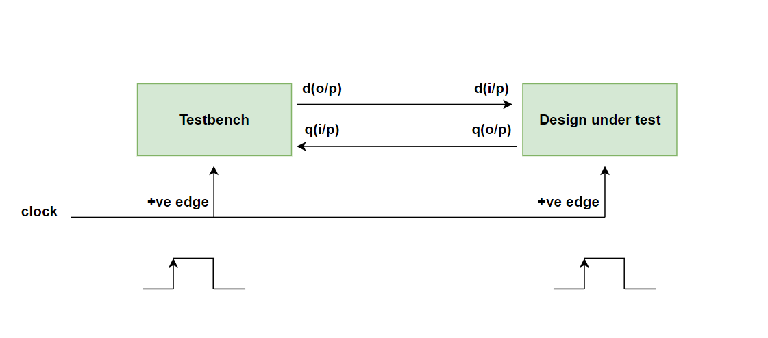
在这个例子中,DUT(时钟块时钟)和测试都在正边沿(接口时钟)触发。在这种情况下,波形输出和显示语句输出不匹配。输出显示在下图中。
示例代码:
DUT 代码:
// module:d_flipflop module d_flipflop(dff.dut intf); //clocking block cd always @(intf.cd) //Non-Blocking assignment intf.cd.q <= intf.cd.d; endmodule : d_flipflop
Interface 代码:
//module: Interface interface dff(input clk); //declare the signals logic d; logic q; //Clocking block for dut clocking cd @(posedge clk); default input #1step output #0; output q; input d; endclocking //modport for dut modport dut(clocking cd); //modport for tb modport tb(input q, output d, input clk);` endinterface: dff
测试代码:
//module: testmodule test(dff.tb intf);//task:drvtask drv;//looprepeat(10)begin//test triggering at posedge@(posedge intf.clk )//randomzing the dintf.d <= $random;$display("test side[%0t]=d_tb_drive:%d q_dut_sample:%d",$time,intf.d, intf.q);end$finish;endtask //calling the task drvinitial begindrv();end endmodule :test
顶层模块
//including the file test.sv and interface.sv `include "test.sv" `include "interface.sv" module top;bit clk=1;initialforever #5 clk = ~clk;//creating interface instancedff intf(clk);//d_flipflop instanced_flipflop t1(intf); //test Instancetest t2(intf);initial$monitor("DUT side [%0t]=d_tb_drive:%d q_dut_sample:%d",$time,intf.cd.d, intf.cd.q);endmodule : top
在下面的输出中,首先给出DUT和测试的正边沿。在这个例子中,在0时间,DUT和测试的输出都是x,然后在10纳秒时,测试随机化d值x为0,这时DUT得到0并给出采样q输出为0,这个时钟周期测试(tb)只随机化值d = 0,但测试(tb)采样了先前的值q = x。在10纳秒时,我的DUT给出输出d = 0和q = 0,而此时我的测试(tb)给出输出d = 0和q = x。现在,在20纳秒时,测试将d值从0随机化为1,此时DUT得到1并给出采样的q输出为1,这个时钟周期测试(tb)只随机化值d = 1,但测试(tb)采样了先前的值q = 0。在20纳秒时,我的DUT给出输出d = 1和q = 1,而此时我的测试给出输出d = 1和q = 0。
输出记录
下图14显示了 d 触发器的输出。

所有时钟周期的 d_ff 输出
下图15显示了 d 触发器的输出波形。

时钟块的优势
- 时钟块提供了测试台和DUT之间无竞争条件。
- 时钟块可以在接口、模块内声明。
- 时钟块帮助用户以更高层次的抽象编写测试台。
- 仿真速度更快。
- 将设计的时钟活动与数据分配活动分离。
- 在设计执行中节省了大量的代码和时间。
虚拟接口
-
虚拟接口是表示接口实例的变量。
-
虚拟接口用于在类中创建接口实例,因为接口是静态组件,而SystemVerilog测试台是动态组件。我们不能直接在类中声明接口,但使用变量 virtual,我们可以在类中声明接口实例。
语法:virtual interface_name instance_name;
interface_name:接口的名称
instance_name:虚拟接口实例的名称,可以在类中使用变量 Ex: vif.variable;
-
虚拟接口必须在类中初始化,指向实际接口。 在类中声明虚拟接口
例如:Virtual intf vif; -
访问未初始化的虚拟接口会导致致命错误。
-
虚拟接口可以作为任务和函数方法的参数传递。
-
虚拟接口可以是类的属性,并且可以通过使用函数参数进行初始化,即它可以在特定类中调用实际接口并在该类中创建接口实例。
例如:function new(virtual intf vif); -
虚拟接口可以作为函数方法的参数传递。 通过使用 new() 构造,在类中调用实际接口 ‘intf’ 来声明虚拟接口,可以在类中的过程或函数参数中使用。
-
在类函数和任务方法内部,可以通过虚拟接口句柄访问接口变量,如 virtual_instance_name.variable;
Example : vif.a
vif 是虚拟实例名称;
a 是类的变量/属性
-
关键字/信号虚拟接口变量在整个仿真时间内表示不同的接口实例。
语法:
interface <interface_name>(); <port_list>; .......... endmodule To connect static(interface module) toto dynamic(class) we use virtual interface class clase_name; virtual <interface_name> <interface_instance>; ....... properties; ..... function() .....endfunction task(); ...... endtask endclass
Example1: Fulladder
全加器的设计代码
//Module:fullinput_adder module fulladder(in_a,in_b,in_c,out_sum,out_carry) ; //Declaration of input variablesinput in_a,in_b,in_c;//Declaration of output variablesoutput out_sum;output out_carry;//continuous input_assignment statementassign out_sum = in_a^in_b^in_c;assign out_carry = (in_a&in_b)|(in_b&in_c)| (in_c&in_a); endmodule:fulladder
全加器的接口模块
interface adder();//declaring the signalslogic in_a,in_b,in_c;logic out_sum,out_carry;endinterface
类内的虚拟接口声明
//class:driver class driver; //Declaration of virtual interface //syntax: virtual interface_name interface_instance;virtual adder vif;//constructor function new(virtual adder vif); //this.vif refer to class driver //vif refer to the function argument this.vif = vif; endfunction //task task run(); repeat(10) begin //interface_instance.variable vif.in_a = $random; vif.in_b = $random; vif.in_c = $random; $display(""); $display("//INPUT:Inputs of full adder \n a=%0b, b=%0b, cin =%0b", vif.in_a,vif.in_b, vif.in_c); #5; $display(""); $display("//OUTPUT:Outputs of full adder \n sum=%0b, carry = %0b\n", vif.out_sum, vif.out_carry); end endtask endclass
全加器的测试模块
`//include the driver file include "driver.sv" //module:test module test(adder intf); //declaring the driver instance driver drv; initial begin //creating the driver instance drv = new(intf); //calling the task run drv.run(); end endmodule:test
全加器的顶层模块
//including the test.sv and interface.sv files`include "test.sv"`include "interface.sv"//module:topmodule top;//creating an instance of interfaceadder intf();// the instance of test t1.test t1(intf);//fulladder DUT instance , connecting the interface signal to instance DUTfulladder dut(.in_a(intf.in_a), .in_b(intf.in_b), .in_c(intf.in_c), .out_sum(intf.out_sum), .out_carry(intf.out_carry));endmodule
下图显示了代码的设计块:

在图16中,驱动器是一个类,在这里我们声明了虚拟接口,因为在类内部我们不能直接调用接口,因为接口是静态组件而类是动态组件。所以这个虚拟关键字被用来在类内部创建实例(它将创建虚拟接口)。在驱动器中,我们生成随机刺激并发送到接口,DUT连接到接口。DUT的输出给予接口。测试块包括类组件,即(driver.sv),顶层模块包括所有组件,如测试、接口和DUT。所有组件的实例都在顶层模块/块中创建。
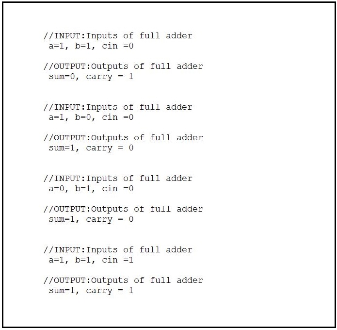
下图显示了全加器的输出:
在图17中显示了全加器的输出,其中 a、b 和 cin 是全加器的输入,sum 和 carry 是全加器的输出。